The technology behind our rotary torque transducers and wireless load measurement sensors.
SGR510/520 series transducers operate using a four-element strain gauge wheatstone bridge, which is connected to a miniature shaft mounted analog to digital converter and microcontroller. The microcontroller conditions and measures the strain gauge bridge output as close to the gauges as possible, eliminating any possible external noise pick up in the gauge wiring.
The shaft mounted electronic module is wirelessly powered by a radio frequency source which drives a stator coil, the output of which is received by a rotor coil on the shaft thus making the system completely contactless. This eliminates the need for slip rings and their associated wear and noise problems.
The shaft microcontroller outputs a digital serial stream that is transferred back from rotor to stator by modulating the impedance of the rotor coil and detecting the impedance changes at the stator coil. A secondary high-performance microcontroller receives the serial stream from the shaft microcontroller, which then performs calibration and temperature compensation before outputting the results digitally via RS232, CAN bus or USB. A 16-bit digital to analog converter also outputs the sensors data as a fully calibrated and compensated analog voltage or current.

Surface Acoustic Wave (SAW) Torque Measurement – How it Works…
The measurement technology for our ‘TorqSense’ RWT410/420, RWT430/440 and RWT450/460 Series Torque Transducers and torque meters is based on the patented technology of measuring the resonant frequency change of ‘Surface Acoustic Wave’ (SAW) devices in a non-contact manner when strain is applied to a shaft to which the SAWs are fixed. The applied torque causes a deformation of the quartz substrate of the SAW device, which in turn causes a change in its resonant frequency. Essentially the SAWs act as ‘frequency dependent’ strain gauges.
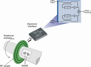 The frequency signal measuring the resonant frequency is coupled via a non-contact RF rotating couple from the shaft to a fixed pick-up and it is the analysis of the difference in resonant frequencies between the two SAW devices, with electronic processing and calibration, that gives a precise indication of the torque transmitted by the shaft. SAW devices have a high immunity to magnetic fields allowing their use in motors. For example, where other analog technologies are susceptible to electronic interference and are not suitable.
The use of this patented measurement technique results in a transducer being able to sense torque bi-directional, with fast mechanical and electrical responses. As the method is non-contact it has also complete freedom from brushes or complex electronics, which are often found in traditional torque measurement systems.
In more detail…
In its simplest form, a SAW transducer consists of two interdigital arrays of thin metal electrodes deposited on a highly polished piezoelectric substrate such as quartz. The electrodes that comprise these arrays alternate polarities so that an RF signal of the proper frequency applied across them causes the surface of the crystal to expand and contract and this generates the surface wave.
These interdigital electrodes are generally spaced at ½ or ¼ wavelength of the operating centre frequency. Since the surface wave or acoustic velocity is 10-5 of the speed of light, an acoustic wavelength is much smaller than its electromagnetic counterpart. For example, a signal at 100Mhz with a free space wavelength of three metres would have a corresponding acoustic wavelength of about 30 microns.
This results in the SAW’s unique ability to incorporate an incredible amount of signal processing or delay in a very small volume. As a result of this relationship, physical limitations exist at higher frequencies when the electrodes become too narrow to fabricate with standard photolithographic techniques and at lower frequencies when the devices become impractically large. Hence, at this time, SAW devices are most typically used from 10Mhz to about 3Ghz.
The operation of a SAW transducer for strain measurement depends on the choice of a suitable piezoelectric substrate, which can be attached to the material to be stressed. The stress results in a strain, which can be in tension or compression. The sensitive axis of the transducer is longitudinal in the direction of wave propagation.
Strain will change the spacing of the interdigital electrodes and hence the operating frequency. For an excitation frequency of 500Mhz, 1000 µ-strain of tension will decrease the frequency by 500 kHz; conversely a compressive strain will increase the frequency by the same amount. To function as an oscillator, the element is used as amplifier feedback. The Q factor of the transducer is high – typically 104. Therefore, by meeting the phase and gain requirement, the circuit will oscillate with very high stability – typically one part in 109. From the technique described it is apparent that the output signal will be in the frequency domain. This has many advantages for a number of applications, particularly in variable speed electrical machines where RF signals cannot be easily contaminated by drive electronic noise.
Optical Torque Measurement Technology
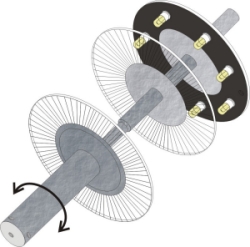
The technology for our Optical ORT230/240 Series Torque Transducers is based on an extensively proven and developed measurement principle whereby two discs with segmented gratings are positioned on the shaft so that the opaque sectors on one disc partially obscure the clear sectors on the other. Light passes through the sectors and is detected by photovoltaic detectors.
The intensity of light beams, which is constantly monitored, is modulated by the applied torque and produces an electrical output that is used to provide a precise indication of the torque transmitted by the shaft. The light intensity is automatically controlled within the transducer body by a monitor cell. Lamps used to provide the light source are selected to ensure they have a long life and high stability.
The use of this measurement technique results in a transducer being able to sense torque bi-directionally. Very high full-scale sensitivity can be achieved with fast electrical responses up to 50kHz and low inertia. As the measurement is non-contact it has also has complete freedom from brushes and complex electronics on the shaft, which are often found in traditional torque measurement systems.
Strain Gauge Technology
The SIT 105/110/120 torque transducers use modern wire foil strain gauge technology with the latest high performance stainless steel shafts. The SIT 105/110/120 strain gauge reaction transducers are designed for operation in any industrial environment.
The Strain Gauge torque transducers offer a range of outputs from mV/V outputs, to ratiometric voltage outputs, to digital data connection via RS232 or USB.
An option of a bench mount housing is available for torque wrench test and calibration.
Wireless Load Measurement – How it Works…
The wireless LoadSense load measurement sensor is a strain gauge stainless steel tension type sensor currently available in 1 Ton to 25 Ton ranges, having an overload capability of more than 150%. It has the capability of wirelessly transmitting its data to one of our compatible displays or data recorders. Data is transmitted 10 times per second in the worldwide licence free 2.4GHz frequency band. A pair of rugged inbuilt antennae ensure the sensor will not get damaged in harsh operating environments. A transmission distance of 100 metres is achievable.
In more detail…
The load sensor contains an internal Lithium Ion rechargeable battery. The battery can be charged from a PC USB port or from an external 11-28 VDC power supply. Depending on transmission data rates and configuration options selected, over 1000 hours battery life can be achieved.
A scheduler allows the user to configure the load sensor to automatically switch on at a certain time of day then return to standby later in the day. This is useful if the sensor is to be attached in a location where it is inconvenient to keep switching on and off every day before and after use. This also allows the user to preserve battery life even further.
The load sensor also contains an inbuilt 32Mbit memory for recording load data locally when an external display or data recorder is impractical. The memory can hold up to 280 hours of data which can then be downloaded to a PC via its USB cable.